24 Vdc Wiring Diagram
Inverter vac 120 vdc circuit diagram simple circiut diagrams parts Sc 24vdc e02 e05 e04 220vac 110vac fuji 440vac 24vac 500vac e03 contactor automationdirect iec vdc coil contactors 25a representative Diagram wire volt motorguide model
WIRE DIAGRAM(MODEL 667) (24 VOLT) - 1999 Electric Trolling Motor 12/24V
Figure 2-25. 24 vdc circuit wiring schematic (145 amp) (sheet 1 of 3) 24 and 36-volt wiring diagrams – trollingmotors.net Supply power dc diagram circuit volt 24 schematic simple
Inverter circuit 120 volt diagram 12vdc 120vac simple vac ac vdc dc 15w power schematic transistor supply source pnp technical
Simple 12 to 120 volt inverter circuit diagramWire diagram(model 667) (24 volt) Iec contactor: 25a, 24 vdc coil voltage (pn# sc-e05g-24vdc50mm dome indicator light.
Wiring trolling volt motor diagram 24v 24 kota minn plug system battery hook electric wire batteries 12v minnkota diagrams motorsVdc conventional circuit constant current 24 volt dc power supply circuit diagram schematicCircuit diagram of a vdc: (a) the conventional vdc and (b) the proposed.
Phase motor diagram reversing control vdc voltage
Indicator wiring dome vdc 50mm buzzerSimple 12 vdc Diagram of 3-phase reversing motor control with 24 vdc control voltage.
.


24 volt dc power supply circuit diagram schematic

50mm Dome Indicator Light - 3 Color Pilot Light with Buzzer - 24 VDC

Diagram of 3-Phase Reversing Motor Control with 24 VDC Control Voltage
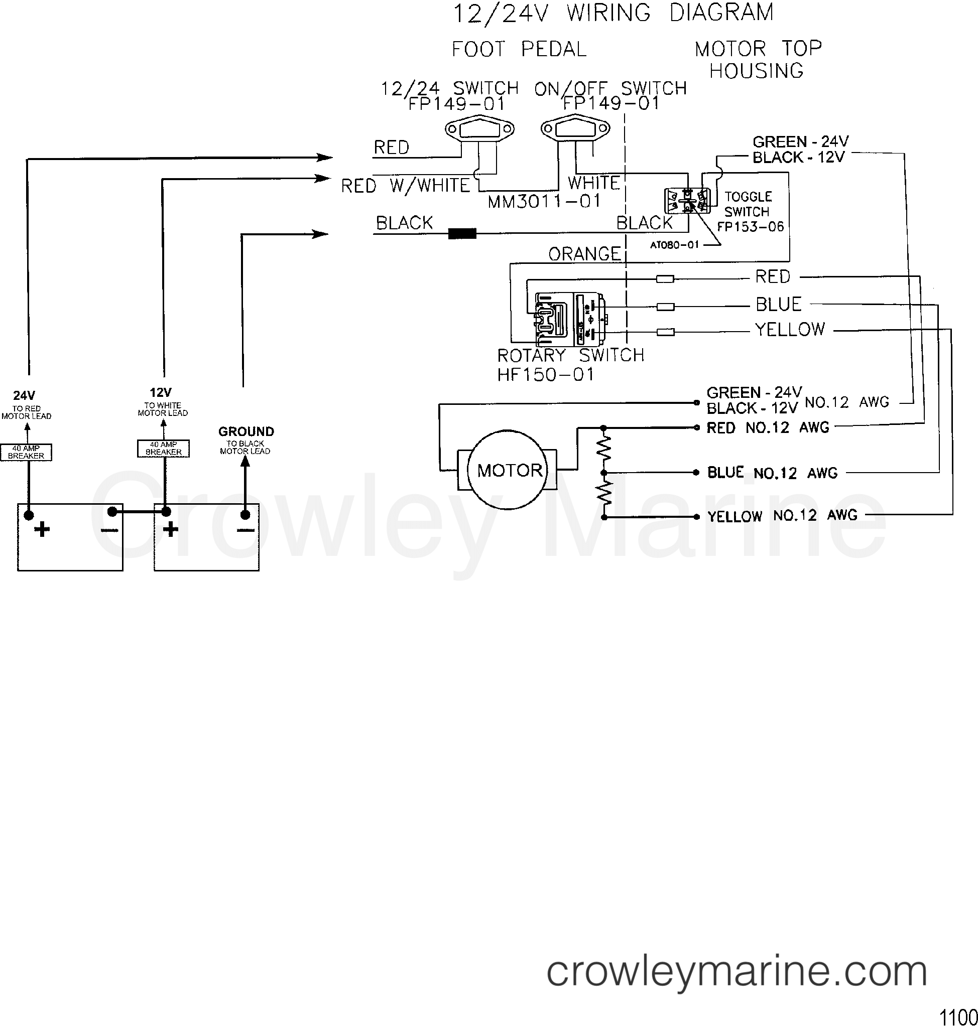
WIRE DIAGRAM(MODEL 667) (24 VOLT) - 1999 Electric Trolling Motor 12/24V

Circuit diagram of a VDC: (a) the conventional VDC and (b) the proposed

24 and 36-volt Wiring Diagrams – TrollingMotors.net

Figure 2-25. 24 vdc Circuit Wiring Schematic (145 AMP) (Sheet 1 of 3)
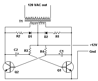
Simple 12 Vdc - 120 Vac Inverter Circiut | Electronic Circuit Diagrams